
How to Build a Parametric Model Using CAD Automation
Learn how to build intelligent, flexible, and reusable parametric models using CAD automation. This guide explains the fundamentals of parametric modeling, automation techniques, benefits, and real-world applications that help engineers reduce design time and improve productivity.
6/15/20264 min read
Introduction
In today's fast-paced engineering environment, companies must develop products faster while maintaining high accuracy and quality. Traditional CAD modeling often requires engineers to manually update dimensions, features, and drawings whenever design requirements change.
As products become more complex, this manual approach can lead to increased design time, repetitive work, and a higher risk of errors.
This is where Parametric Modeling and CAD Automation play a crucial role.
By combining parameter-driven design with automation tools, engineers can create smart models that automatically update based on user-defined values, significantly improving efficiency and consistency.
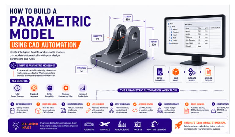
What is a Parametric Model?
A parametric model is a CAD model whose geometry is controlled by parameters such as dimensions, formulas, relationships, and design rules.
Instead of creating a fixed model, engineers define variables that drive the design.
For example:
A bracket model may contain parameters such as:
Length
Width
Height
Hole Diameter
Material Thickness
When any of these values change, the entire model updates automatically without requiring manual modifications.
What is CAD Automation?
CAD Automation involves using APIs, scripts, macros, and custom applications to automate engineering tasks within CAD software.
Automation can:
✔ Create models automatically
✔ Modify parameters and dimensions
✔ Generate drawings
✔ Export files
✔ Create BOMs
✔ Validate designs
When combined with parametric modeling, automation enables engineers to generate multiple design variants quickly and accurately.
Why Use Parametric Modeling with Automation?
Organizations increasingly use parametric automation because it offers several advantages.
Faster Design Changes
Update a few parameters instead of redesigning the model manually.
Improved Accuracy
Relationships and rules ensure consistent design updates.
Better Reusability
One model can generate multiple product variants.
Reduced Engineering Effort
Automation eliminates repetitive design activities.
Increased Productivity
Engineers spend more time on innovation and less on manual modifications.
CAD Software Supporting Parametric Automation
Popular CAD platforms used for parametric automation include:
CATIA
Siemens NX
Creo Parametric
SolidWorks
Solid Edge
These platforms provide APIs and automation tools that support parameter-driven design workflows.
Step-by-Step Guide to Building a Parametric Model
Step 1: Define Design Requirements
Start by identifying the dimensions and features that are likely to change.
Examples:
Length
Width
Thickness
Hole Size
Fillet Radius
These values will become the driving parameters of the model.
Step 2: Create the Base CAD Model
Build the initial geometry using standard CAD modeling techniques.
Focus on creating a clean and stable model structure that can accommodate future changes.
Step 3: Create Parameters
Define user parameters inside the CAD software.
Example:
Length = 200 mm
Width = 100 mm
Thickness = 10 mm
These parameters will control the geometry of the model.
Step 4: Link Dimensions to Parameters
Associate dimensions with the defined parameters.
For example:
Extrusion Length = Length
Hole Diameter = Thickness × 2
Pocket Depth = Thickness × 0.8
This creates intelligent relationships within the design.
Step 5: Establish Design Rules
Add engineering logic to ensure valid configurations.
Examples:
✔ Minimum wall thickness requirements
✔ Standard hole sizes
✔ Manufacturing constraints
✔ Material-specific design rules
These rules help prevent design errors.
Step 6: Automate Parameter Updates
Use automation tools such as:
CATIA Automation
NX Open API
Creo Toolkit
Solid Edge API
VBA Macros
Python Scripts
C# Applications
Automation can update parameters automatically based on user input, Excel files, databases, or external systems.
Step 7: Generate Multiple Design Variants
Once the model is parameter-driven, automation can create multiple configurations automatically.
Example:
A company producing brackets in different sizes can generate dozens of design variations using a single parametric model.
This eliminates repetitive modeling work.
Step 8: Automate Drawing Generation
After updating the model, automation can create:
Engineering Drawings
Dimensions
Annotations
BOM Tables
Manufacturing Documentation
This significantly reduces drafting time.
Step 9: Export Manufacturing Files
Automation can automatically generate:
PDF Files
STEP Files
DXF Files
STL Files
Excel Reports
This streamlines communication between design and manufacturing teams.
Real-World Example
Consider a company manufacturing industrial support brackets.
Without automation:
Engineers manually create each size variation
Drawings are generated individually
Documentation is updated manually
With parametric CAD automation:
✔ Enter required dimensions
✔ Model updates automatically
✔ Drawings generate instantly
✔ Manufacturing files export automatically
The result is faster project completion and improved consistency.
Benefits of Parametric CAD Automation
Reduced Design Time
Projects can be completed significantly faster.
Improved Consistency
All generated models follow the same design standards.
Reduced Human Errors
Automation minimizes manual intervention.
Easy Product Customization
Generate new product variants quickly.
Better Scalability
Handle large volumes of design configurations efficiently.
Industry Applications
Parametric CAD automation is widely used in:
Automotive Industry
Vehicle component design and product configuration.
Aerospace Industry
Structural component generation and documentation.
Manufacturing Industry
Standard part creation and production documentation.
Tool & Die Industry
Mold design and fixture automation.
Industrial Equipment Design
Custom machinery and configurable products.
Best Practices
To build successful parametric models:
✔ Use meaningful parameter names
✔ Keep model structures simple and organized
✔ Document design rules clearly
✔ Test multiple configurations
✔ Follow company modeling standards
✔ Validate generated outputs regularly
These practices improve model reliability and maintainability.
Career Opportunities
Engineers skilled in parametric modeling and CAD automation are increasingly in demand.
Popular roles include:
CAD Automation Engineer
Design Automation Engineer
CAD Customization Developer
NX Open Developer
CATIA Automation Engineer
Creo Automation Engineer
Combining CAD expertise with programming knowledge creates strong career opportunities in modern engineering organizations.
Future of Parametric CAD Automation
Emerging technologies are making parametric automation even more powerful:
✔ Artificial Intelligence (AI)
✔ Generative Design
✔ Digital Twins
✔ Smart Manufacturing
✔ Cloud-Based Engineering Platforms
Parametric models will continue to play a key role in the future of engineering automation.
Conclusion
Parametric modeling combined with CAD automation enables engineers to create intelligent, reusable, and highly efficient design workflows. By automating parameter updates, drawing generation, and documentation processes, organizations can reduce design time, improve accuracy, and accelerate product development.
As industries continue to embrace digital engineering, learning parametric CAD automation is becoming an essential skill for future-ready engineers.
Contact Us
💼 At Descode Solutions, we specialize in:
✔ CAD Automation Training
✔ CATIA, NX, Creo & SolidWorks Automation
✔ Real-time Industry Projects
✔ CAD Customization & API Development
📈 Learn smarter. Automate faster. Accelerate your career in CAD automation.
📩 Looking to master parametric modeling and CAD automation? Connect with us today!
📞 Phone: +91 9544 123 321
🌐 www.descodesolutions.com
📧 info@descodesolutions.com
CAD Automation Training
Expert CAD Automation training for professionals and students
OUR COURSES
Contact
info@descodesolutions.com
(+91) 9544 123 321
Copyright © 2026 Descode Solutions LLP
NX Customization
CATIA Customization
AutoCAD Customization
Solidworks Customization
Solid Edge Customization
Revit Customization
Inventor Customization
Creo Customization